Inverter Circuit Board Diagram
Oct 16, 2021 #1 lucius c newbie. A suitable alternative is to use this 200w inverter circuit.
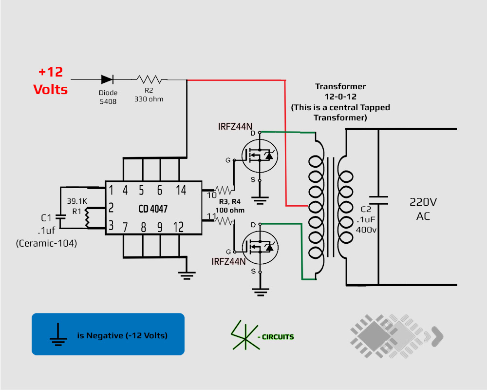
12 Volt to 220 Volt Inverter
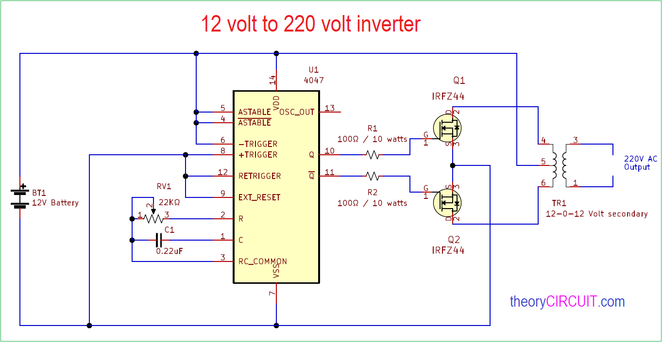
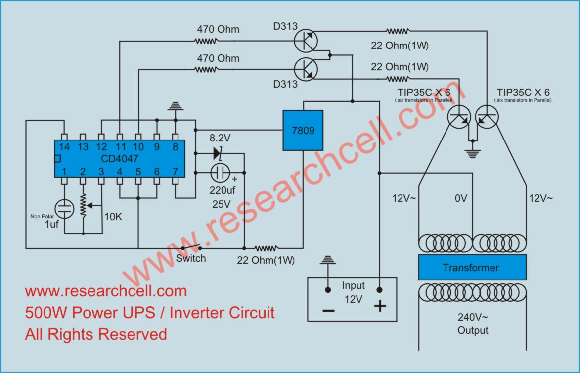
This circuit is quite simple because we use ics and mosfets.

Inverter circuit board diagram. Joined oct 13, 2021 messages 2 helped 0 reputation 0 reaction score 0 trophy points 1 activity points 21 pleas i need full circuit diagram for dsp pic300f2010 control board circuit diagram. A wiring diagram is a simple visual representation in the physical connections and physical layout of your electrical system or circuit. The square wave is fed to ic 4017 which will convert to modified sine wave at 50hz at 50% duty cycle.
You do not have it now. Start date oct 16, 2021; In the two circuit diagram below, just use 2 transistor, 2 resistors, and one transformer only.
The following diagram is the basic design diagram of inverter circuit. Dc/ac pure sine wave inverter jim doucet dan eggleston jeremy shaw mqp terms abc 20062007 advisor: Schematic diagram of mig welding setup machine schematics service arc 200 circuit pdf smps inverter diagrams c3000i tig 3000i ac dc welder electronic.
Also 500w inverter circuit for you. All these loads will come through this mcb. The output terminals of the inverter and the tweezers were scarred.
If you think that this circuit is not good enough. Two types of inverters currently exist on the market; Some models have the same control driver floors only igbt.
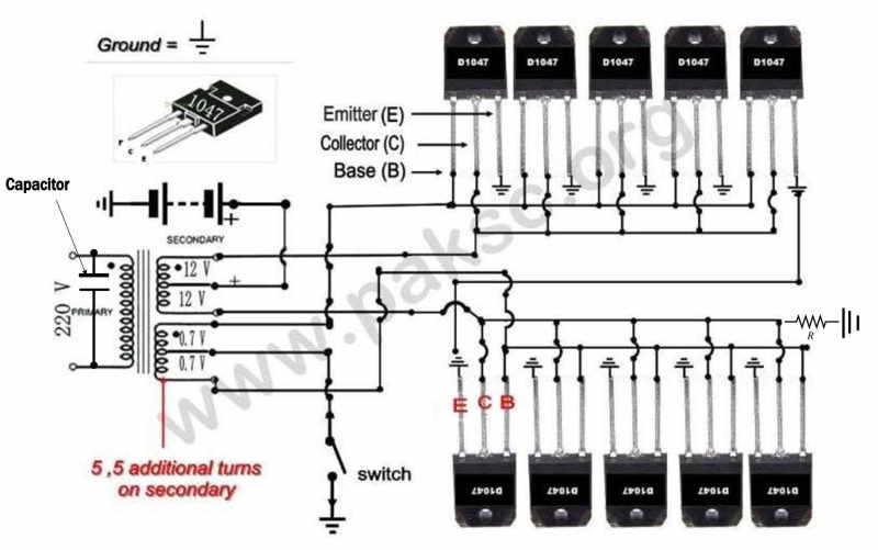
This basic inverter circuit can handle up to 1000watts supply depends the t1, t2 and transformer used. Microtek inverter circuit board pcb card control इन वर टर क र ड in delhi natasha industries id 20489554248. Sinewave ups using pic16f72 homemade circuit projects.
The circuit will convert 12v dc to 120v ac. N1 & n2 gates of ic 4049 are employed as an oscillator. A modified square wave inverter outputs a wave similar to a square wave with a delay in between cycles, while a sine wave inverter outputs a true sine wave.
Here is the circuit section, get understanding the basics of this power inverter, diy an inverter now. This power inverter is designed for. As discussed on the video, the left block of schematic refers to what's on the egs002 board, and the one on the right is the circuit that we would have to build in order to build a fully functional inverter.
There are 920 inverter circuit diagram suppliers, mainly located in asia. Nagaland genius electronics microtek inverter 24x 7 circuit diagram. (the working principle of a variable frequency.
If you have understood well. And whether inverter circuit diagram is ac, {2}, or {3}. But we have details that need to be learned.
Sort by date sort by votes oct 16. Microtek inverter circuit diagram pdf electrical learner. This is accomplished through an inverter circuit using electronic components.
For charging these batteries the schematic and wiring diagrams are shown below. Luminous 600va inverter circuit diagram. To understand well how to construct a solar inverter, it is vital to study how the circuit operates through with the help of following steps:
It comprises a cd4047 multivibrator (ic1), irf250 mosfets (t1 through t8), transistors and a few discrete components. Modified sine wave inverter circuit diagram the circuit consists of ic 555 which is tuned to generate frequency at 200hz (square wave) at 50% duty cycle. Presently, you will notice that the vfd schematic is a popular type of output transistor used for a control system.
N1 n2 gates of ic 4049 are employed as an oscillator. 7 rows 1000w 12v dc home power inverter circuit board design. There are many basic electrical circuits for the power.
In this circuitry, the 6 scrs are linked in this sequence scr1, scr6, scr2, scr4 scr3 scr5, and capacitors from c1 to c6 offer the commutation needed through scr. It is hard to find equipment. Luminous eco volt+ 800va/900va circuit diagram in pdf.
The inverter application requires two outputs that are 180 degrees out of phase. They can convert 12vdc from battery to 220vac or 120vac to apply small light bulbs or lamps max 10 watts. This electrical device that transforms the ac power supply frequency, the vfd circuit, comprises three parts.
First, i recommend simple working principle of the inverter. I barely made adjustments for this one since the datasheet sample schematic would serve well for a 16 mosfet configuration too.

Designing a Solar Inverter Circuit Tutorial LEKULE
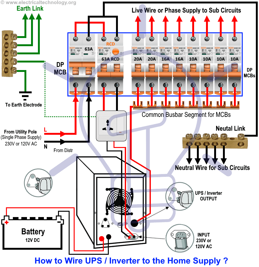
Automatic UPS / Inverter Wiring & Connection Diagram to

Transformerless Dc To Ac Inverter Circuit Diagram

How to Make a Simple 200 VA, Homemade Power Inverter

Egs002 Inverter Circuit Diagram Pdf / Thebackshed Com
How to Build a 12 VDC to 220 VAC Power Inverter (UPS)

Sg3525 Inverter Circuit Diagram Circuit diagram
PWM Sinewave 5kva Inverter Circuit
![]()
How to Make a 200 Watt Transformerless Inverter Circuit
Inverter Circuit Diagram

100W Inverter Circuit Schematic EEWeb Community

Luminous Inverter Circuit Diagram Manual Home Wiring Diagram

Pure Sine Wave Inverter Frequency Inverter Circuit Diagram

12V to 220V Inverter (Circuit Diagram&PCB layout
How to Make an Inverter by yourself?

Make This 1KVA (1000 watts) Pure Sine Wave Inverter
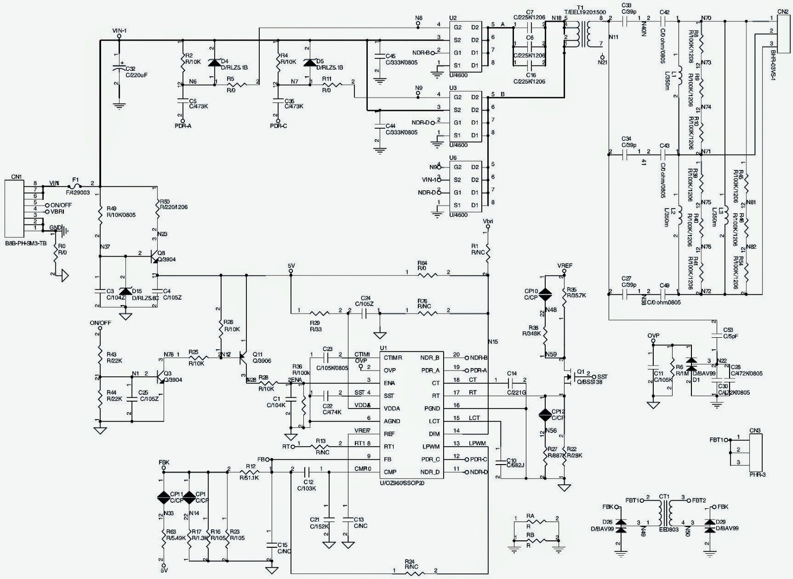
Electro help LCD TV BACKLIGHT INVERTER BOARD SCHEMATICS

Inverter Circuit Diagram Board Home Wiring Diagram

Pin on Electronics