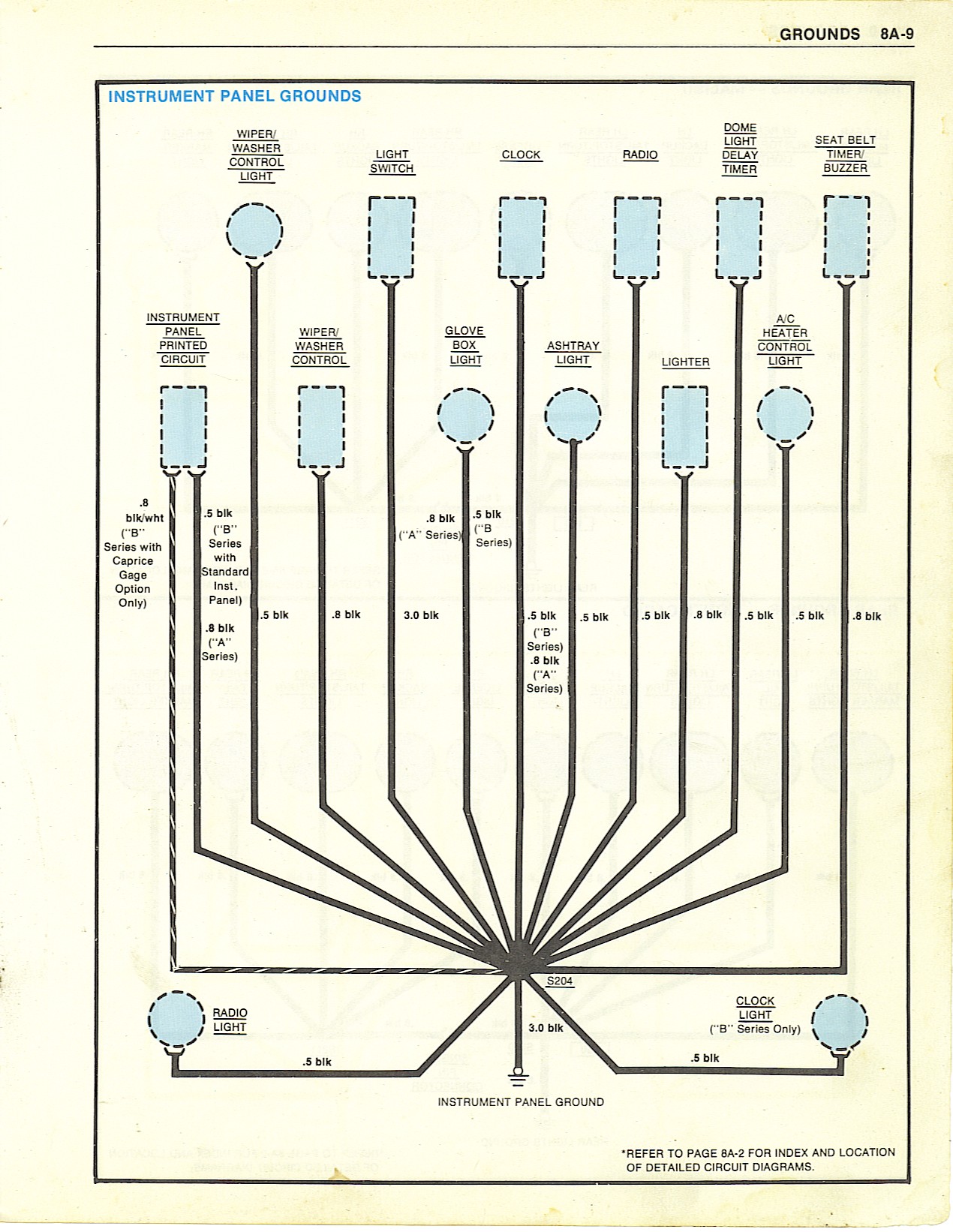
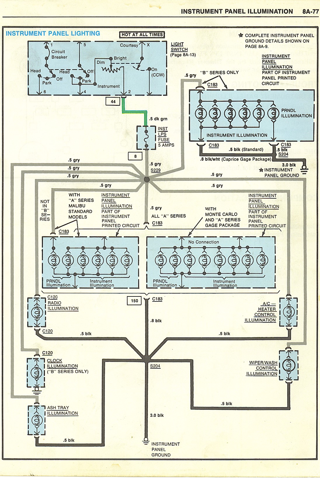
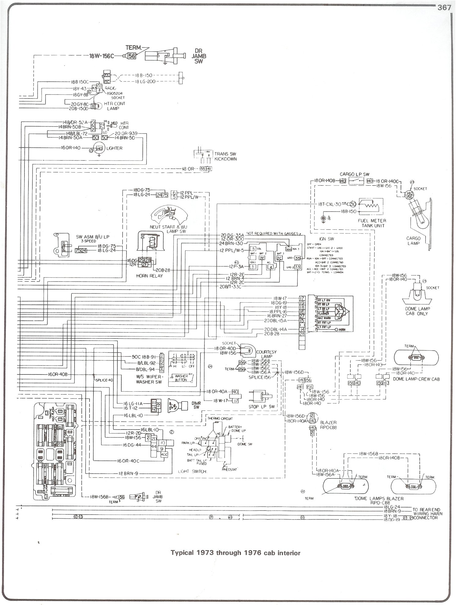
Instrument Panel Wiring Diagram
If it does not work, then check for around 7 to 9 volts at the wire for the sender. Fine how to install electrical panel board inspiration best.

Volkswagen GTI 1992 Instrument Panel Wiring Diagram All
I allready had the wiring diagram from de ec that you send me, and i need the codes/colors of the wire of the plugs in the instrument panel terninal.
Instrument panel wiring diagram. January 6, 2015 page 5 new instrument panel wiring always disconnect the vehicle battery before wiring any gauge. Panels wiring diagram for yanmar/volvo multiguage panels b. Compartment, instrument panel, or body wiring harness location.) use the id number with the parts location table that follows each wiring diagram.
I have discovered an issue with the indicators on my spartan and i could do with a 'map' before i delve in. Basically, they work fine when the ignition is off, left, right and hazards work as they. Same for the temperature sender.
Even though the electrons don’t “care” how neatly the wires are laid in place, human beings who must maintain the system certainly do. I pulled the whole cluster to get my speedo fixed. If you do not have it, it is either the cluster or wiring.
Here's some other '67 diagrams, including all wiring, is here: The attached photo may or may not help you. A wiring diagram usually gives more information about the.
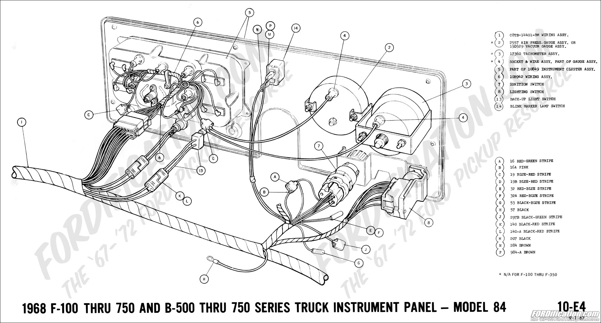
I need to plug the original instrument panel (hilux 1985) in the new 2rz fe wire. Some panels are not available with all engines. 1967 mustang wiring and vacuum diagrams on a stock '67 dash, the speedometer is on the left and the tach is on the right.
Instrument panel wiring diagram de beer member 1997 ford bantam 408,000 miles i want to fix the wires on my bakkie and dont know where the wires must go some of it burned do you have the same problem? Signs that represent the elements in the circuit and lines that represent the. Here are a number of highest rated instrument panel wiring diagram pictures upon internet.
We identified it from trustworthy source. This will refer you to a harness connector diagram in section g where the component connector’s location is shown. 1) connect a good chassis ground to the black [position 1] wire of the gauge harness.
Need the instrument cluster wiring diagram to my 1987 300d turbo. (light switch's source is terminal 4) if this is correct the interior light should work when the light switch is in the middle or down position and panel light switch is in down position. Remove the sender switch wire and check the gauge and then ground the wire as well.
Yes no saturday, march 10th, 2012 at 8:51 am 1 reply please login or register to post a reply. While doing so the 15 prong socket (sits behind the fuel/ oil pressue/ and engine temp gauge) popped off exposing all the wirings coming out of the hole. Its submitted by management in the best field.
The panel switch is energized through terminal 1 when light switch is in middle or down position. These types of diagrams are normally found with home appliances and automobile electrical systems (figure 12). Then ground the wire and the gauge should go the other way.
Wiring for instrument panels with transmission pressure gauge 12 position terminal wiring diagram for ac dc inc. Only component connectors are shown in the system diagram. I thought i had them all in the correct hole, but the only problem.
There is much to be said for neatness of assembly in electrical signal wiring. Hi, does anyone know where i can get a wiring diagram for the driver's instrument panel in a cvr(t)? Wiring diagrams show the component parts in pictorial form, and the components are identified by name.
This section contains the line drawings and the wiring diagrams of our instruments panels that are available with our engines. That will test the gauge. The instrument cluster also contains the body control module and is referred to as the cab compartment node (ccn).
A wiring diagram is a kind of schematic which utilizes abstract pictorial icons to show all the interconnections of components in a system.
[DIAGRAM] 1967 Mustang Instrument Cluster Wiring Diagram

Wiring Diagrams
VY Instrument Cluster Pinout/Wiring Diagram Just Commodores

Cadillac De Ville 1984 Instrument Panel and Accessories

2009 Bracket, relay. Micro, mini. Trim [all trim codes

Instrument Cluster Wiring Diagrams Of 1987 Ford Mustang

After ten minutes driving the temperature gauge go up and
56010108AE Genuine Mopar WIRINGINSTRUMENT PANEL

[DIAGRAM] Yanmar B Type Instrument Panel Wiring Diagram

Gauge cluster Instrument Panel wiring.

ELECTRIC Wiring Diagram Instrument Panel Chevy trucks

1999 Subaru Impreza 2.0 Wagon Instrument Panel Wiring Diagram

I need the wiring diagram for the instrument panel on a
Wiring Diagrams

Where can I find an instrument cluster wiring diagram for

Wiring Diagram For Instrument Panel

Instrument Cluster Wiring Diagrams Of 1987 Ford Mustang
How to remove instrument panel dash ford pickup
Chevy Truck Instrument Cluster Wiring Diagram MotoGuruMag