Intermatic T103 Wiring Diagram
Mar 15, · intermatic t timer. Wiring for model t103 intermatic timer

WiringDiagramForT104Timer RAUR.US
Fj cruiser serpentine belt diagram;
Intermatic t103 wiring diagram. May use two wires of the same size and type. Typical wiring diagram clock motor / volt 3 wire supply to loads ground line 2 line 1 a 2 4 gr. To wire switch follow diagram above.
Use solid or stranded copper only wire with insulation to suit installation. Intermatic t103 timer wiring diagram intermatic t103 timer wiring diagram wiring instructions: A wiring diagram is a streamlined traditional pictorial representation of an electric circuit.
Pioneer mvh 290bt wiring diagram; Intermatic t103 wiring diagram assortment of intermatic t103 wiring diagram. Remove 1/2 inch of insulation from wire ends.
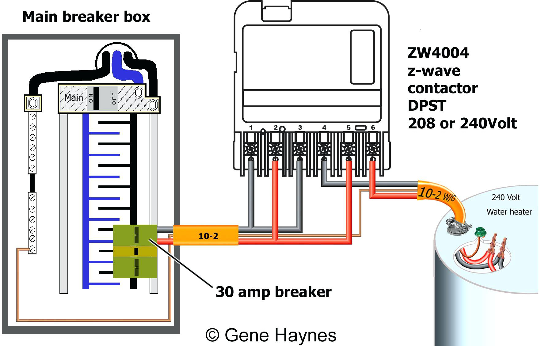
Use solid or stranded copper conductors only. Black to terminal 1, red to terminal 3, white to terminal a, ground to ground terminal. In this new partnership intermatic will serve as the sole representative of pedoc product sales within the united states.
Intermatic t103 timer wiring diagram 31.08.2018 1 comments purchased a new t outdoor timer. To wire switch follow diagram above. Intermatic timer t103 wiring diagram triing to install an intermatic t103 timer to run 3 1000w hps.
Additionally, 1 & 3 are labeled 'line', and 2. I purchased an intermatic t timer switch and am unable to get the clock running. I purchased an intermatic t timer switch and am unable to get the clock running.
Currently, there are two white wires from a & 1 leading to the timer itself. In the intermatic t103 box is a wiring diagram as attached. May use two wires of the same size and type.
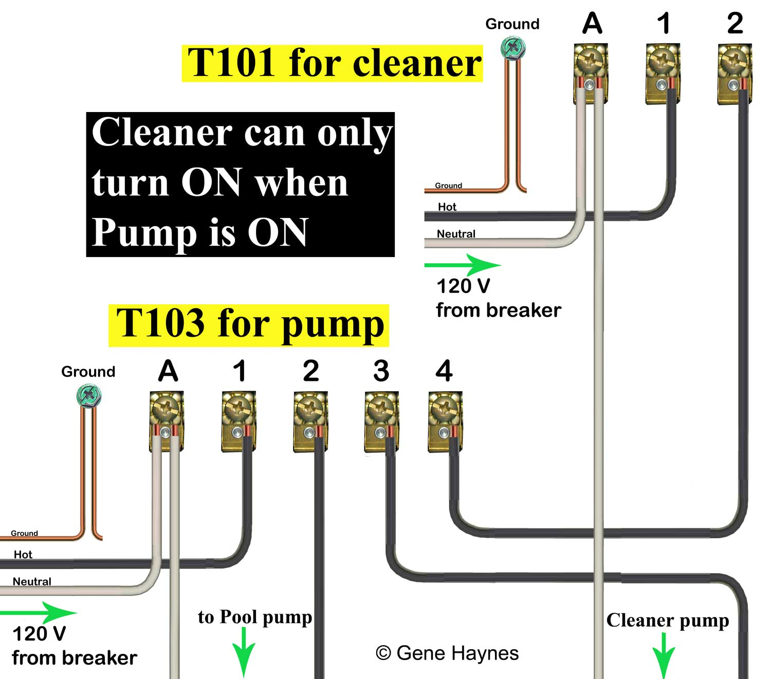
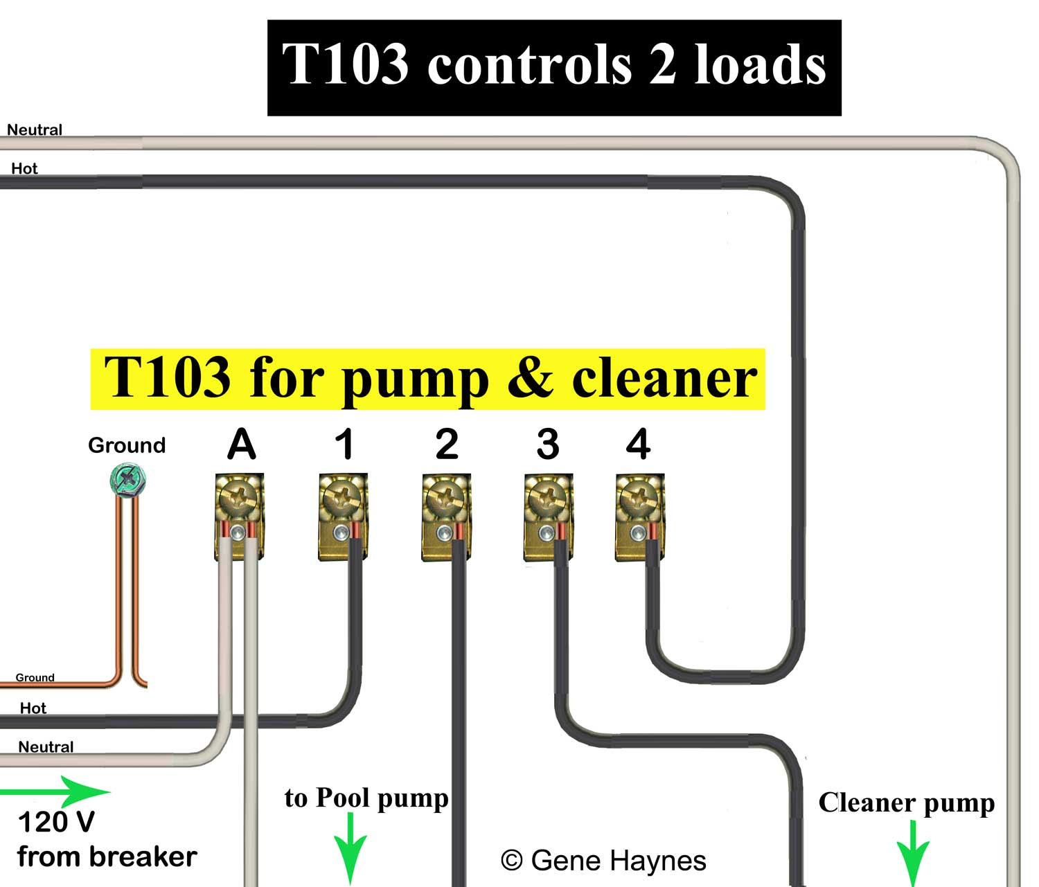
How to wire in an intermatic t103 time switch. My question is, in which locations (1 thru 4) do i wire the black and. On the inside, there are 5 screws, labeled a, 1, 2, 3, and 4.
Currently, there are two white wires from a & 1 leading to the timer itself. Use solid or stranded copper intermatic incorporated. To wire switch follow diagram above.
Detailed wiring diagram 917.288070 lawn mower; The t series mechanical time switch has proven it can stand the test of time. Ground to ground, and the switched black line on terminal 2, and unswitched on.
This is a wiring diagram for the t is this how you have it wired?. Source will be 110v(220v unavailable) the ballasts are all 110v. Little tikes road ninja wiring diagram;
My question is, in which locations (1 thru 4) do i wire the black and. The volt clock timer motor is connected internally to the a (neutral). A wiring diagram is a straightforward visual representation with the physical connections and physical layout of your electrical system or circuit.
I need to know the easiest way to wire this. Use solid or stranded copper only wire with insulation to suit installation. Stevenbbarto on intermatic t103 wiring
It shows the elements of the circuit as streamlined shapes, as well as the power as well as signal links between the devices. Assortment of intermatic t103 wiring diagram. 2011 nissan rogue serpentine belt diagram;
Outgoing, the 2 white wires are wirenutted with the white incoming line and again all tied to terminal a. It shows the elements of the circuit as streamlined shapes, as well as the power. Remove 1/2 inch of insulation from wire ends.
Model t103 dpst typical wiring diagram 120 vac input equipment ground line 1 neutral clock motor to loads. In imitation of infuriating to remove, replace or repair the wiring in an automobile, having an accurate and detailed intermatic t103 wiring diagram is necessary to. Use solid or stranded copper conductors only.
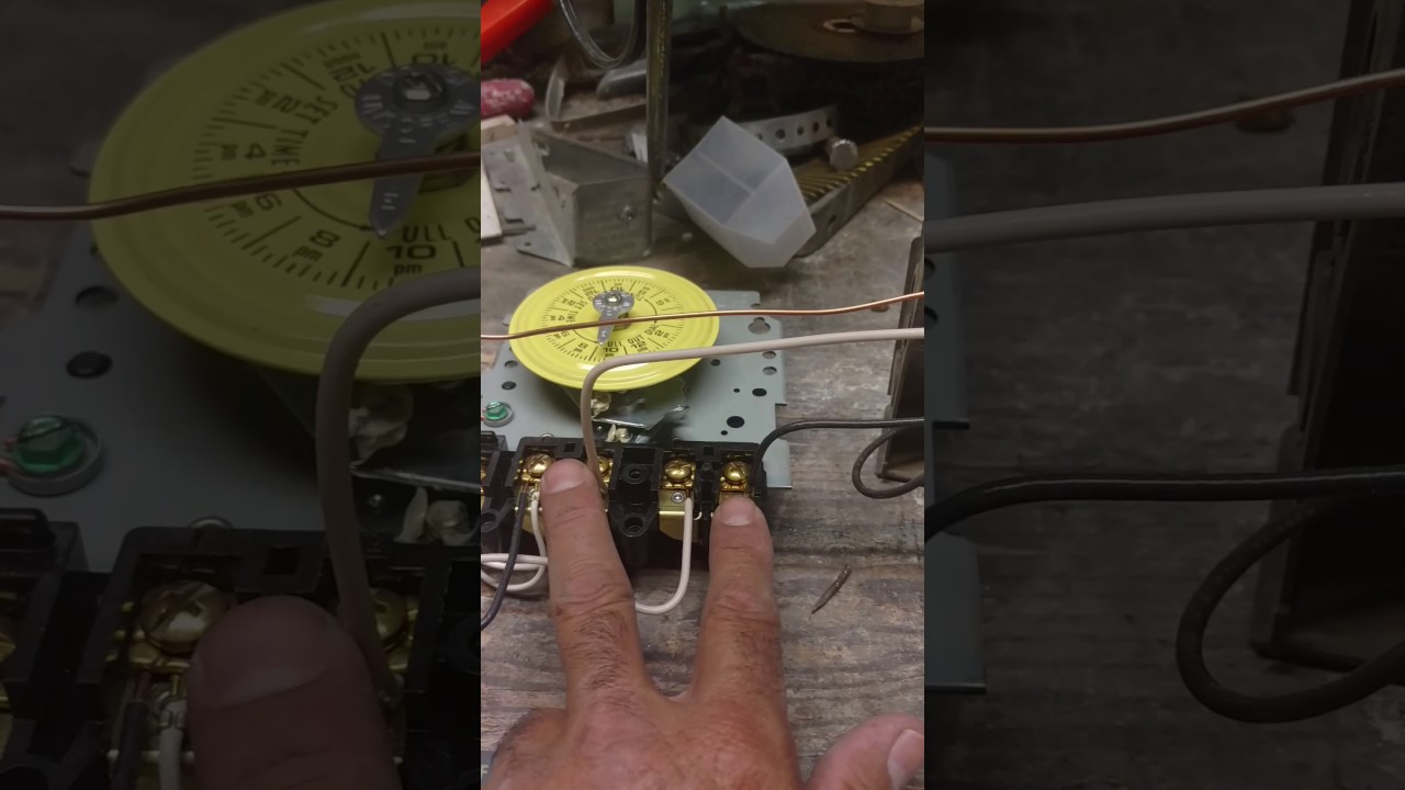
Under a minute vid showing how to wire these timers (110/120v model) A wiring diagram is a streamlined traditional pictorial representation of an electric circuit. The wiring diagram got me so confused.
The wiring diagram for that timer is misleading. Sunl brute 200cc motorcycle schematic wiring diagram; On intermatic t103 wiring diagram.
Intermatic t103 wiring diagram building electrical wiring representations reveal the approximate areas as well as affiliations of receptacles lights as well as permanent electrical solutions in a building. I bought an intermatic t103 and wire it as follows power to 1 3 poles lights 2 4 a jumper from.
![]()
Intermatic T103 Wiring Diagram Free Wiring Diagram

Intermatic T103 Wiring
Intermatic T103 Wiring Diagram Download Wiring Diagram

How To Wire Intermatic T104 And T103 And T101 Timers in
Intermatic T103 Wiring Diagram Download Wiring Diagram

Intermatic T101 Wiring Diagram
Intermatic T103 Wiring Diagram Download Wiring Diagram
Intermatic T103 Timer Wiring Diagram

Intermatic T103 Wiring Diagram SCRAPPIN2LILPRINCESSES


Intermatic R8806p101c Wiring Diagram Collection
How to wire T103 timer

Intermatic T103 Wiring

Intermatic T103 Wiring Diagram Free Wiring Diagram

intermatic timer switch wiring diagram Wiring Diagram
Intermatic T103 wiring YouTube
T103 Wiring Diagram Complete Wiring Schemas

Intermatic T101 Timer Wiring Diagram General Wiring Diagram

Intermatic T103 Wiring Diagram Download Wiring Diagram
